This page will focus on different machines that I have worked on. A big part of my job is to figure out what about the machine is causing it to fail and to design a solution to fix it. A major takeaway from this work has been seeing the designs that have failed and understanding why. With these projects, I gain experience with GD&T, designing, and machining.
Auto-Ridgelock Cell Project
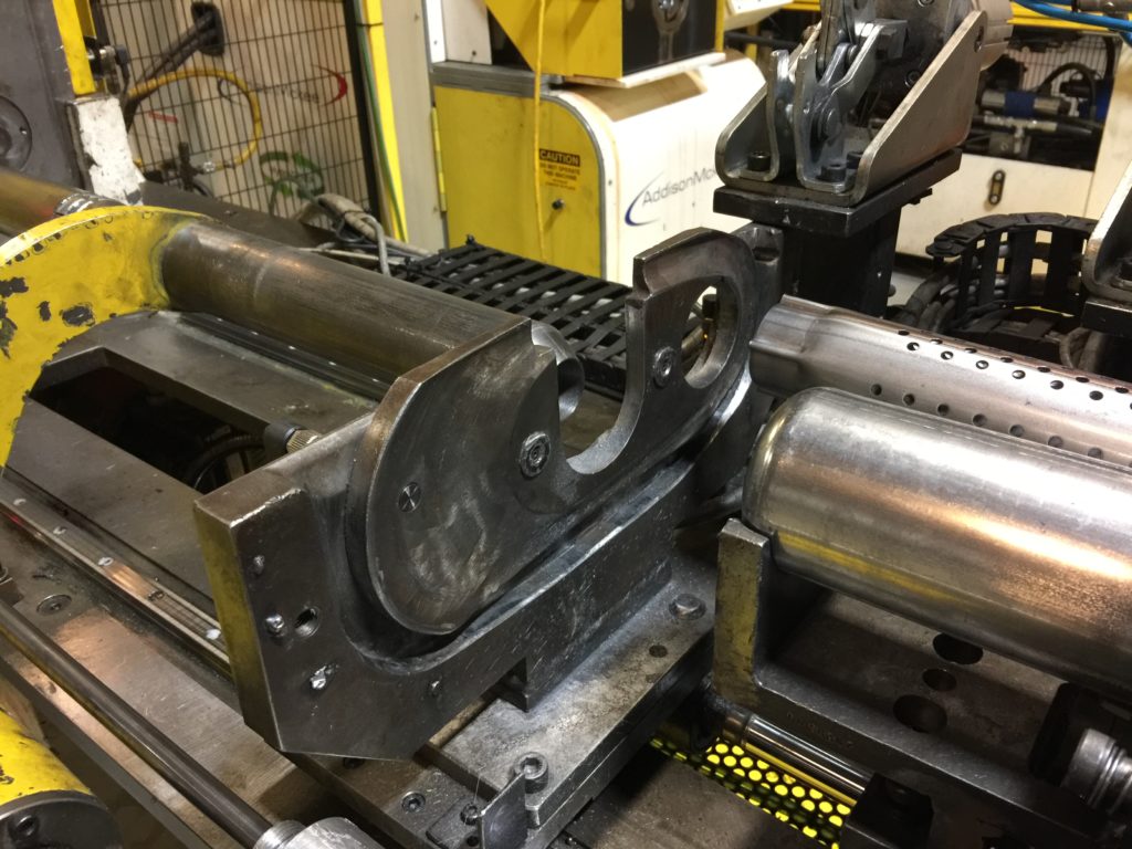
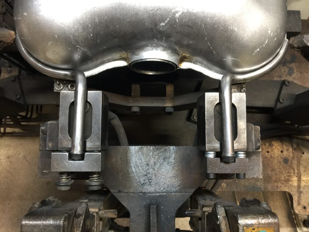
During a five-week summer shutdown, I was given an opportunity to work on this cell. This cell had been causing a lot of problems with poor quality parts and many breakdowns. Most parts were coming out a little bent which was causing difficulty loading them into muffler halfshells. This cell had 2 robots to put 5 parts together at a rate of about 60 parts per hour.
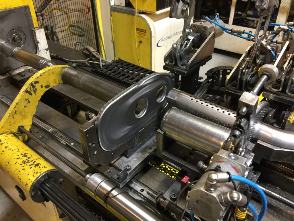 The machine press fits the the pipe with the crimped end into the baffle. Before the update was done, there was spring loaded plate on the front side of the baffle to hold it in place and let the robot load.
 The hole on the left is where the press fit is going to happen but it’s completely unsupported! When I jogged the machine through its steps in manual, the top of the baffle laid over. There was a mandrel to reform the part whose mounts can be seen in the previous picture but the damage was already done. I was certain that this was causing excessive forces on the machine components increasing time between failures and causing poor part quality. I knew that the hole must be supported all the way around.
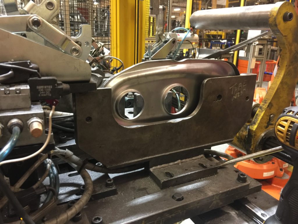
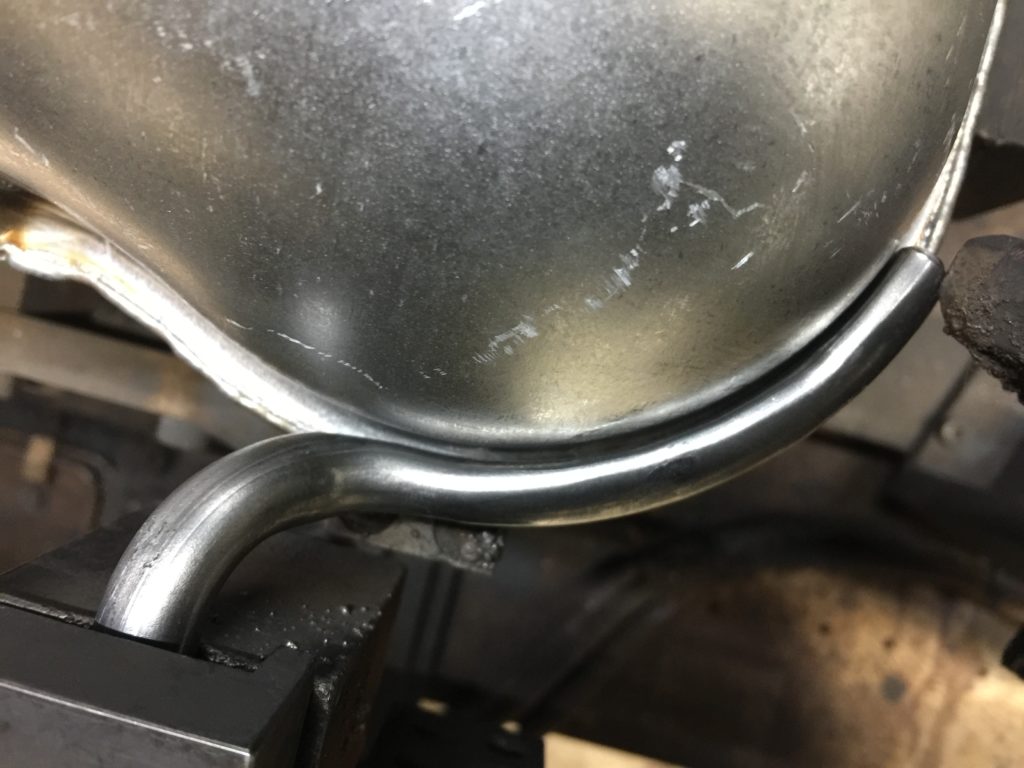
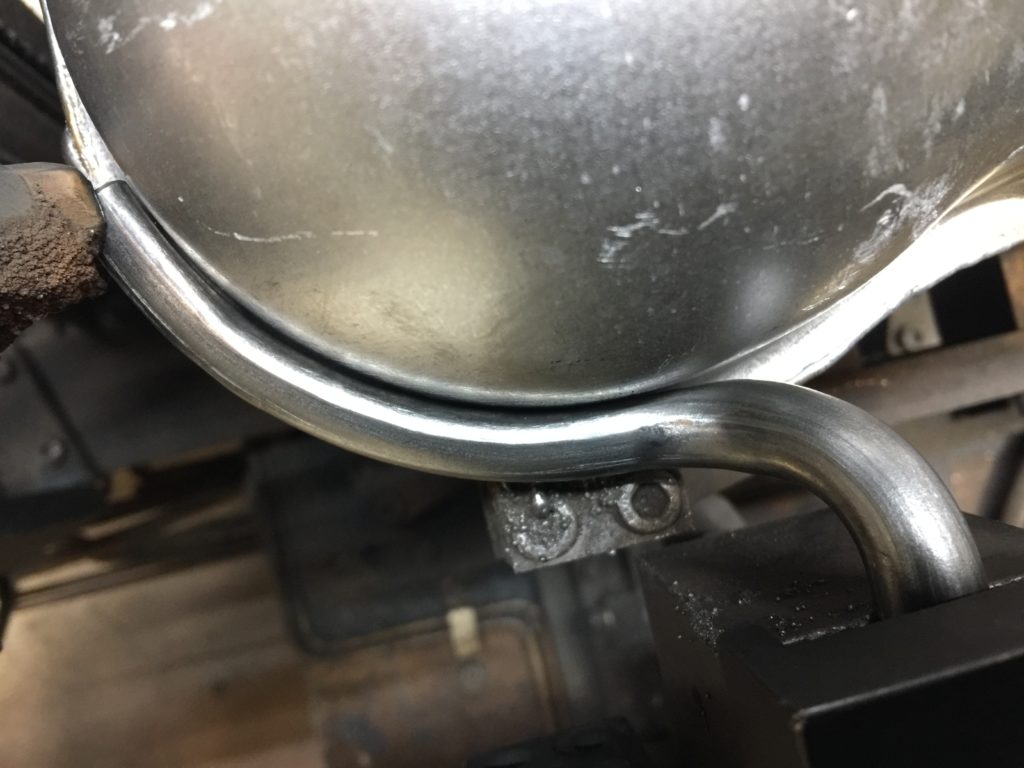
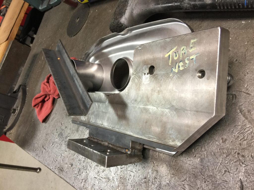 I cut a piece of pipe that was long enough the accept the press fit, welded it to some angle stock, and bolted it to the existing fixture place. I then put this back in the machine and was able to fully run a part like this. While this part still required some further tweaks, the subassembly reference gauge showed that this part was much straighter than before.
Without the spring loaded plate, the robot needed a new way to install the baffle into the fixture. I figured I could put magnets on the plate that I would use to support the back of the baffle. I designed the backplate in SolidWorks using the 3D part file to extract the contour. I then programmed the machining with CAMWorks, set up the CNC, and ran the part.
Bent Pipe Weld Fixturing
A bend adjustment was made and a new batch of pipe that was still within tolerance was causing some trouble on the gauge. I first witnessed the problem occurring and noted that the pipe looked a little crooked. Then I checked that the pipe was within tolerance. I then went to the weld fixture and noted that the pipe displayed a slight angularity there. For some background, the pipe is designed with datums at either end because these locations are critical to assembly. The rest of the pipe has a 4mm positional tolerance along its central axis.
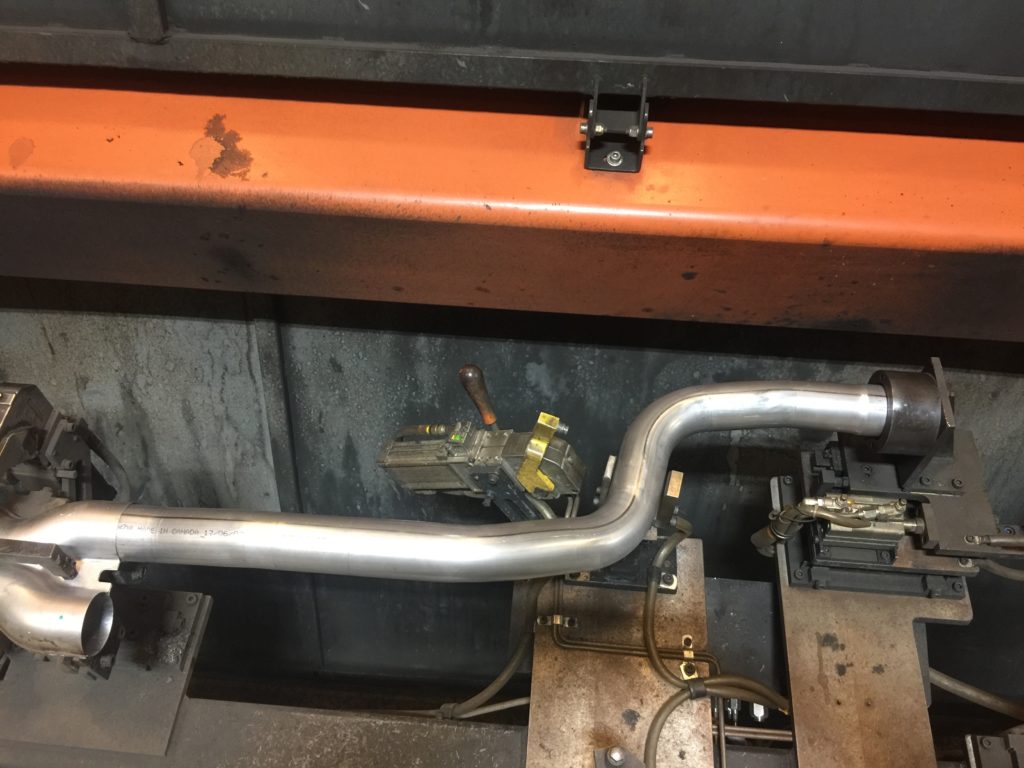 While the current fixture does do a good job of datuming the ends of the pipe, it has a clamp that pushes the pipe against a hard stop in the middle at one of the bends. The fixture was essentially making this point a datum which caused distortion near the actual datums. Is this particular scenario, the clamp was causing the end of the pipe to angle downward.
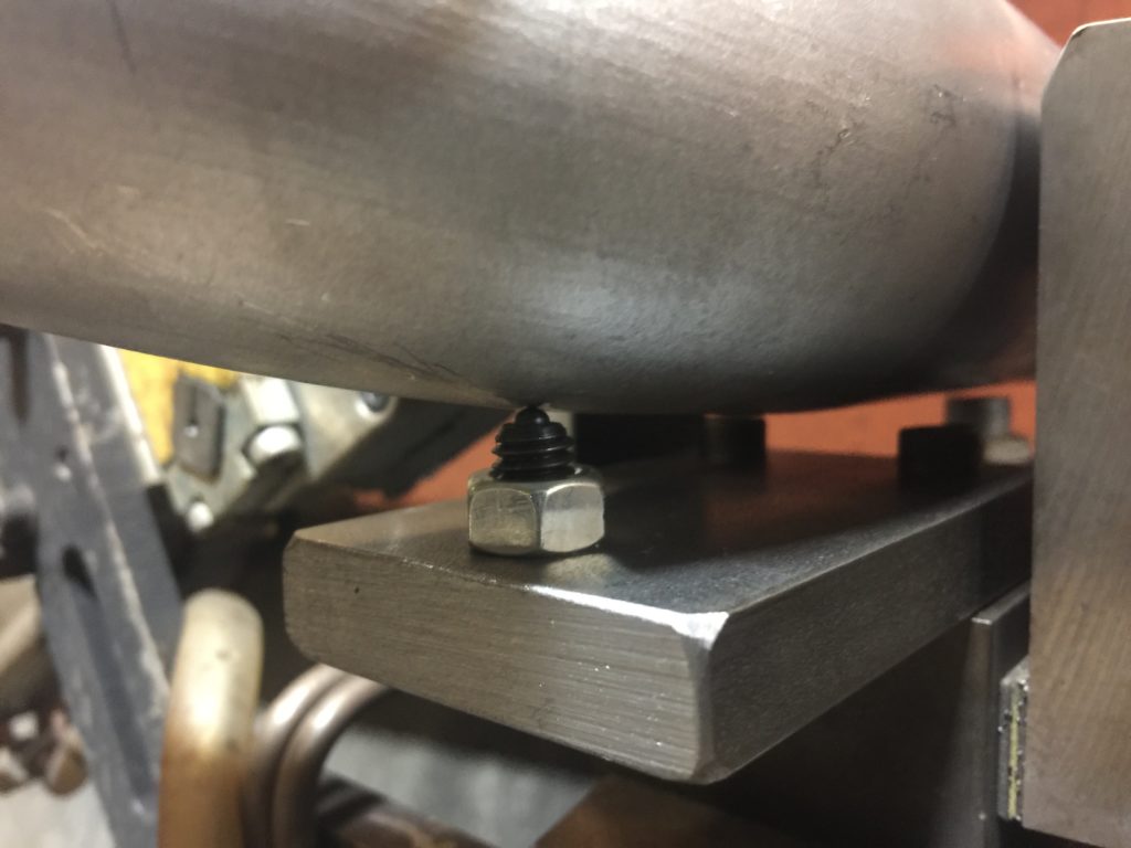
 I had to think about how to better control the rocking motion the pipe has when held from only the two datums while allowing for the profile tolerance of the rest of the pipe. I chose to add a hard stop near one of the ends control the rocking in one direction. I put a spring plunger on another part of the pipe so that it would rotate it towards the hard stop.
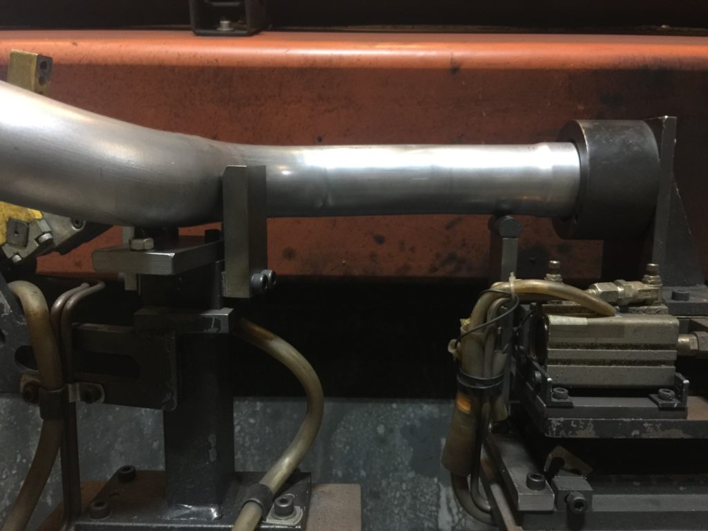
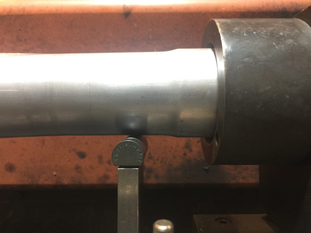 I chose to put the hard stop here because the upsizing of the end of the pipe is a very consistent process so I knew this part of the pipe would be in the same position regardless of other variations in the bends.
 The spring plunger pushes the pipe onto the hardstop and its motion accounts for variations in the bends. I left the vertical hardstops in place because they help with both loading and keeping the positional tolerance in that direction.
Bracket Welding Fixture Poke Yoke
 At this station, hanger brackets are welded onto the muffler. It is critical that the union of the stamping and the rod be tight all around to get a good weld. The old fixturing is on the right side, where the end of the rod is held by a hard stop which was not accounting for any part variation. Part of the standard work was to push the bracket against the muffler while clamping to ensure good contact. A step like this is easily skipped by an operator and was apparent in the scrap. The modification to the fixture was a slight redesign of the existing the hard stop and putting it on a spring loaded slide to ensure a good seating and account for parts that could be slightly shorter.
 With the old fixture with no spring loading, this is the gap the operator was watching for.
 With the spring loading, the bracket seated fully every time and the scrap and repair rates from this station went to nearly zero.